l pacchetto software LASIT per il controllo della marcatrice comprende:
– Il software di controllo che include un ambiente CAD per la creazione delle lavorazioni e la loro realizzazione, FlyCAD.
– Il software per la manutenzione del sistema FLyControl.
Il sistema è normalmente fornito con il software installato. Nel caso sorga la necessità di reinstallare uno o più componenti del pacchetto software, attenersi alle procedure di seguito descritte.
Per scaricare l’ultima versione di FlyControl vai qui
Per avviare l’installazione richiedi la password tramite chat o email.
Prerequisiti per l’istallazione di FlyCad
Occorre che sia installato il software FlyControl e che questo venga avviato almeno una volta e opportunamente configurato – se non hai installato FlyControl guarda il paragrafo precedente.
Il Preview è uno strumento che viene utilizzato per visualizzare, all’interno del campo di marcatura, dove verranno effettuate le lavorazioni e di conseguenza anche dove posizionare gli oggetti da marcare. La marcatrice, quando esegue un Preview, utilizza un laser di bassa potenza, di colore rosso e non dannoso, se non per visione diretta (Laser di classe 2).
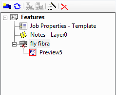
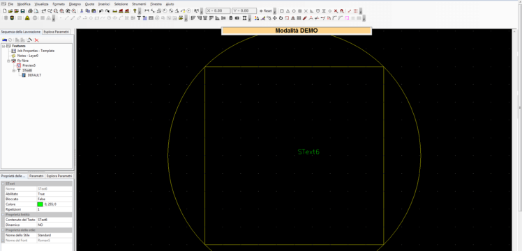
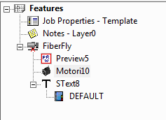
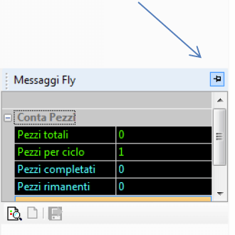
Il Preview viene visualizzato di default in ogni nuovo disegno nel CAD all’interno dell’albero delle lavorazioni in alto a sinistra, come si vede nell’immagine in basso.
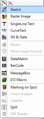
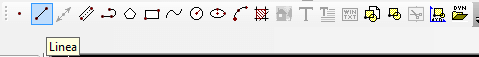
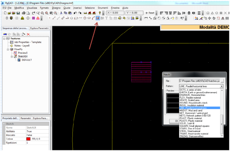
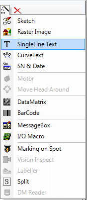
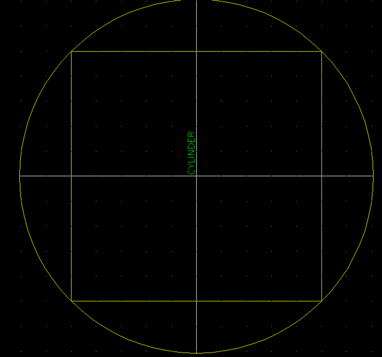
II Preview può essere utilizzato per disegnare linee, rettangoli, poligoni, polilinee, ellissi, o anche cerchi. Puoi selezionare tutte queste forme dalla barra Draw (vedi immagine in basso) che si trova in alto.
N.B. Quando FlyCad viene lanciato per la prima volta, la barra Draw si trova sulla destra della pagina in verticale. Può essere spostata e inserita insieme alle altre per una questione di comodità. Per saperne di più riguardo le toolbar di FlyCad guarda il video.
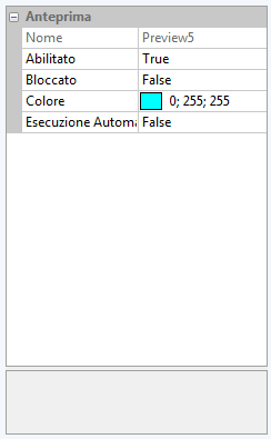
La prima proprietà permette di abilitare e disabilitare l’oggetto selezionato cliccando su TRUE o FALSE. Una volta disabilitato l’oggetto scomparirà dal piano di lavoro CAD ma sarà salvato nell’albero delle lavorazioni e potrà essere riutilizzato in un altro momento. La seconda permette di bloccare o sbloccare l’oggetto (non potrà essere modificato a meno di sbloccarlo di nuovo). Una volta bloccato un oggetto, questo resterà visibile nel piano di lavoro CAD ma non potrà essere selezionato e tutte le modifiche effettuate non influiranno sulla sua posizione né sulle sue caratteristiche. La terza consente di cambiare il colore utilizzato nella visualizzazione a video. L’ultima proprietà permette di impostare l’esecuzione in automatico del Preview appena viene caricato il disegno.
Una funzione molto pratica del Preview è quella dello “Shape preview”. Qualsiasi oggetto abbiamo disegnato, dalla forma più semplice ai testi, immagini o DataMatrix più complessi, può essere visualizzato sul particolare da marcare precisamente com’è, ossia senza l’ausilio di forme che lo contengono.
Una tale funzione risulta molto vantaggiosa quando bisogna marcare delle geometrie molto complesse e formate da più elementi dal momento che è possibile vedere l’oggetto direttamente sul particolare da marcare e valutare bene la posizione dei suoi elementi compositi. Una volta creato il disegno e caricato premendo sull’icona del semaforo in alto, basta cliccare con il tasto destro sull’oggetto e selezionare “Shape preview”.
Tutti i tipi di file grafici, ma anche file PDF, l’importante è che siano stati creati da un programma vettoriale e non siano invece immagini (Jpg, etc.) salvate come PDF.
Abbiamo realizzato un video nel quale illustriamo tutte le opzioni che il software LASIT FlyCAD mette a disposizione per modificare e personalizzare il testo.
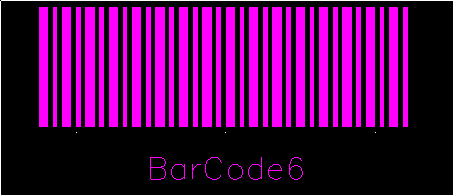
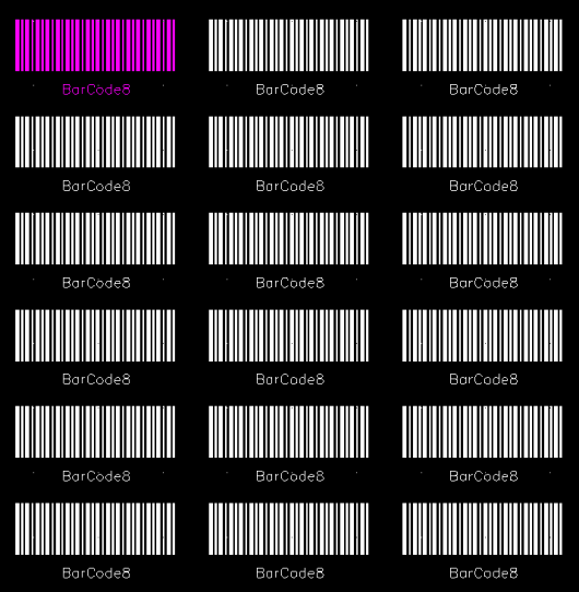
Il codice a barre è un insieme di elementi grafici a contrasto elevato disposti in modo da poter essere letti da un sensore a scansione e decodificati per restituire l’informazione contenuta.
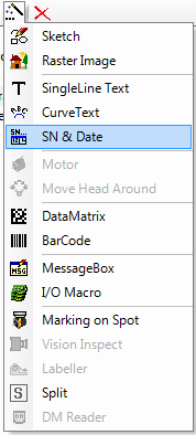
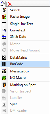
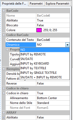
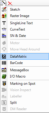
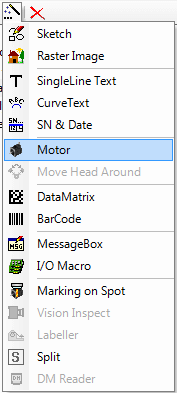
Puoi selezionare questa funzione dal menu a tendina che si apre cliccando sull’icona della bacchetta magica nell’albero delle lavorazioni. Nell’Albero delle lavorazioni comparirà un nuovo oggetto, il cui nome per default è BarCode# (dove # indica un numero progressivo).
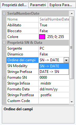
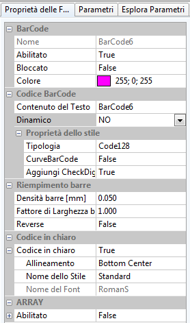
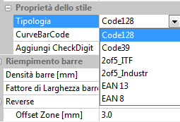
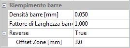
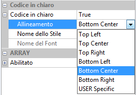
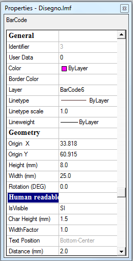
Se il nuovo oggetto viene selezionato, nella sottostante finestra “Proprietà delle features” puoi modificare le proprietà del codice a barre.
Proprietà Barcode
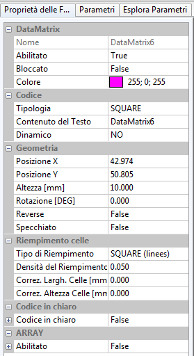
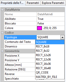
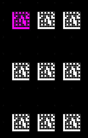
Il DataMatrix è un sistema di codifica delle informazioni bidimensionale (2D) che si sviluppa come un cruciverba. A differenza del codice a barre che si sviluppa in una sola dimensione, il DataMatrix permette di codificare molti più caratteri per mm² e di avere una certa ridondanza, grazie ad un sistema di ECC (Error Coding & Correction) per cui se il codice si rovina limitatamente (fino al 30%) lo si può ancora leggere.
Puoi selezionare questa funzione dal menu a tendina che si apre cliccando sull’icona della bacchetta magica nell’albero delle lavorazioni. Nell’Albero delle lavorazioni comparirà il nuovo oggetto, il cui nome per default è DataMatrix# (dove # indica un numero progressivo).
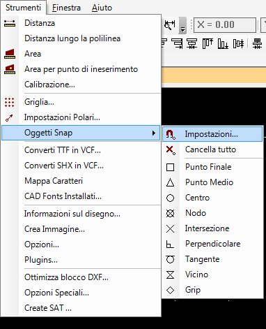
Lo Snap ad oggetto è una funzione che ti permette di disegnare con precisione e più velocemente. Tale funzione utilizza degli “snap ad oggetto” che non sono altro che una specie di calamita che ci permette di fare interagire i vari oggetti del disegno tra loro secondo dei punti stabiliti, come l’estremità o il centro di un oggetto, evidenziando questi punti con degli appositi simboli, che compariranno al momento del loro intervento, nel punto interessato del disegno.
Per utilizzare tale funzione basta selezionare dal menu Strumenti Oggetti Snap. Puoi utilizzare diversi punti di interazione, come il punto finale, punto medio, centro ecc.
Per saperne di più riguardo questa funzione, ma soprattutto riguardo il suo impiego pratico guarda il video che trovi qui.
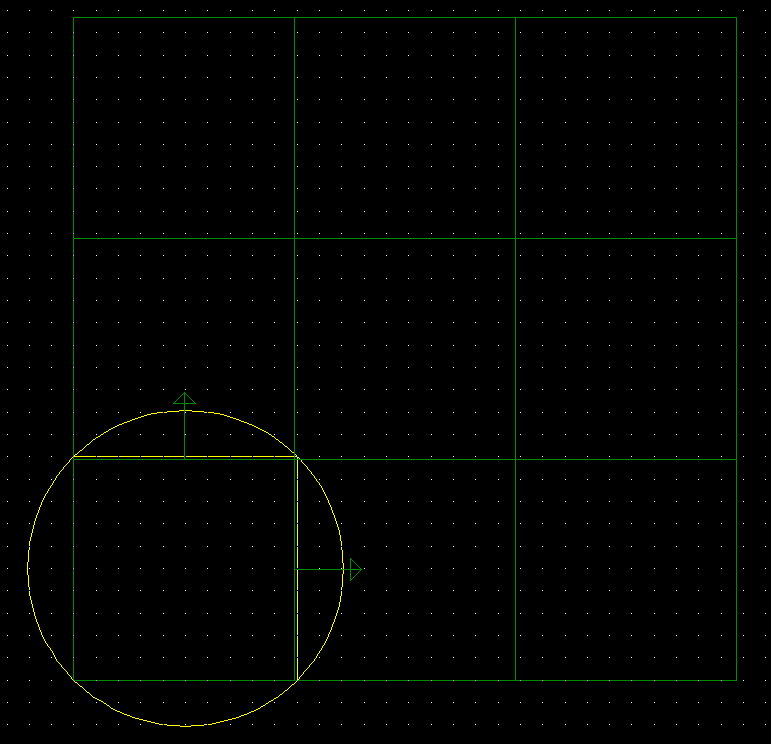
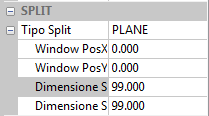
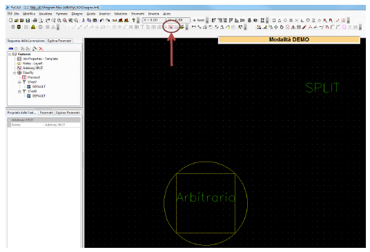
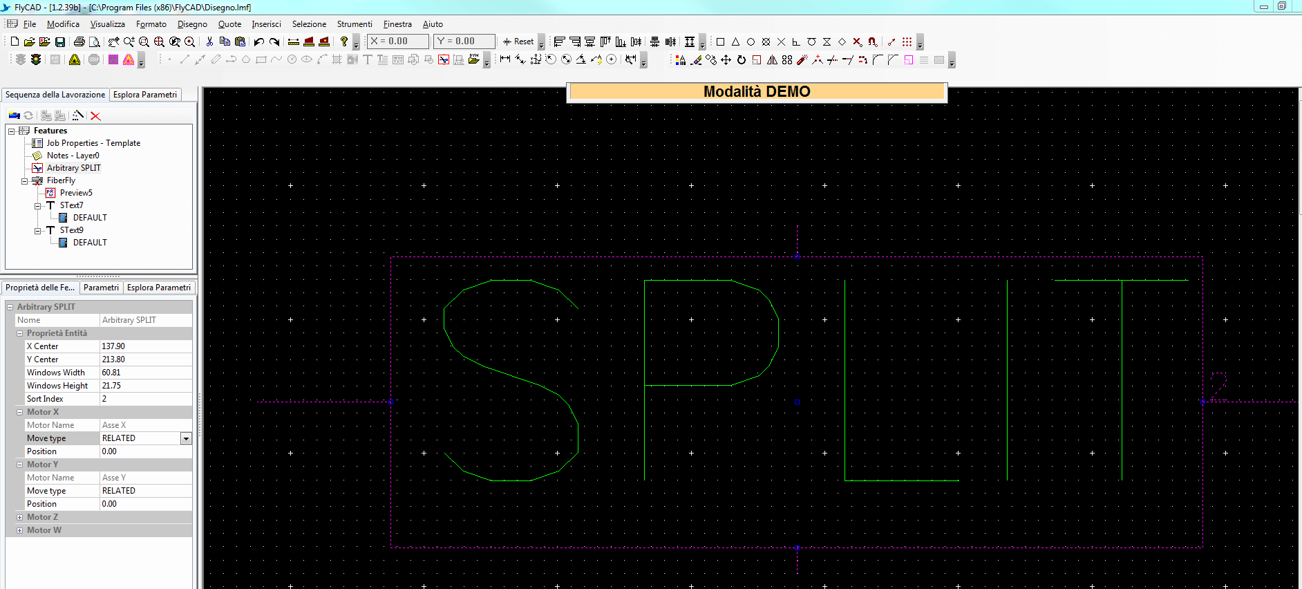
La funzione SPLIT permette di marcare e/o incidere perfettamente e uniformemente qualsiasi oggetto che va oltre l’area di marcatura: grazie al movimento degli assi XY: la testa laser (e di conseguenza il fascio laser) si sposta in dipendenza dell’oggetto marcando sempre al centro dell’area di marcatura.
La massima area di marcatura utilizzando la funzione SPLIT ovviamente è in dipendenza della corsa degli assi che abbiamo a disposizione.
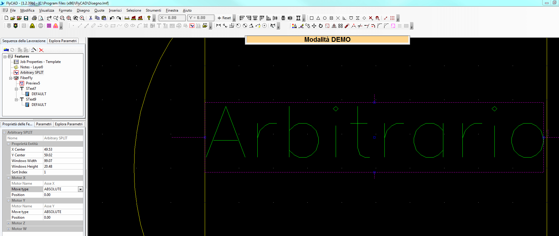
Per impostare lo SPLIT seleziona Job Features nell’albero delle lavorazioni e cerca la sezione SPLIT. Dal menu a tendina potrai scegliere una delle seguenti opzioni.
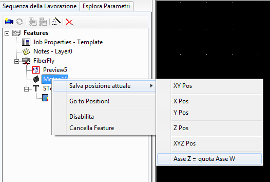
NB è importante selezionare la posizione iniziale X e Y dello Split in Job Features. Se imposti la posizione degli assi da un nodo motore, andranno in conflitto (l’asse andrà avanti e indietro).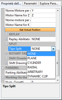

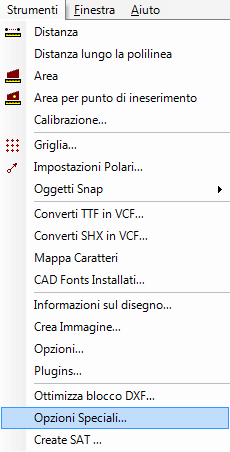
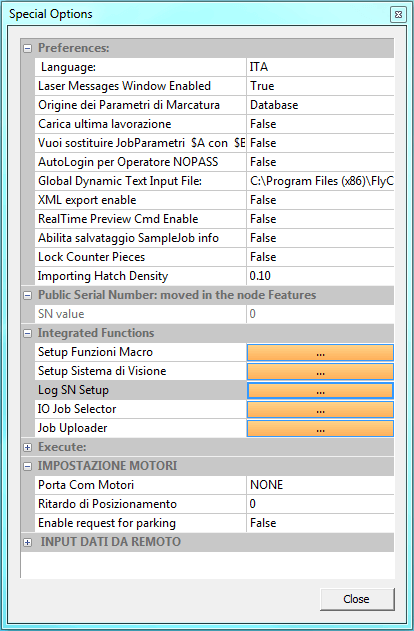
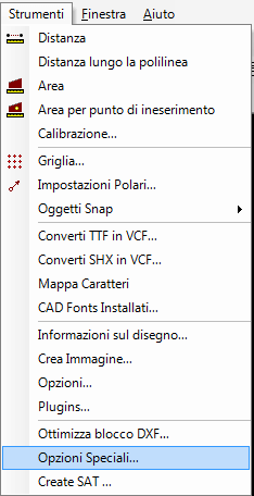
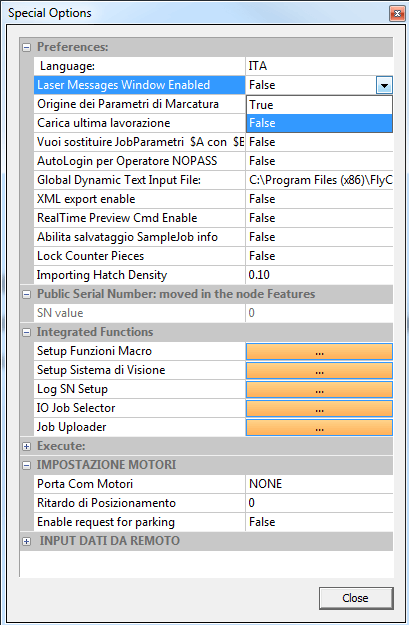
Dal menu Strumenti seleziona Opzioni speciali.
Problemi di compatibilià
L’applicazione “flycad.exe” non ha i permessi di amministratore e/o è attiva qualche spunta di compatibilità con le versioni precedenti di Windows.
In questo caso il passo correttivo da compiere è:
Se “flycad.exe” non ha già impostato i permessi di amministratore per essere eseguito, allora impostare i permessi di amministratore in questo modo: Tasto destro del mouse sulle proprietà di “flycad.exe” -> Compatibilità ->Modifica impostazioni per tutti gli utenti -> spuntare Esegui questo programma come amministratore.
Nel caso in cui è spuntata qualche compatibilità con le versioni precedenti, allora:
Tasto destro del mouse sulle proprietà di “flycad.exe” -> Compatibilità -> Modalità compatibilità e TOGLIERE LA SPUNTA da Esegui il programma in modalità compatibilità per.
________________________________________
Troppi Record
Una versione vecchia di FlyCAD ha creato troppi record nella tabella “tb_publicSN”.
In questo caso il passo correttivo da compiere è:
Avviare “AutomaticBackup.exe”, selezionare il comando Execute SQL dal menù opzioni e selezionare lo script “resetSN.sql”.
________________________________________________
File di log troppo grande
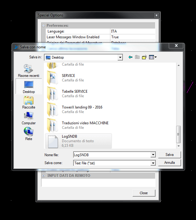
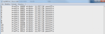
Il file di Log del Database FlyControl ha assunto dimensioni elevate.
In questo caso il passo correttivo da compiere è:
Avviare AutomaticBackup.exe, selezionare il comando Minimize Flycontrol Log File dal menù opzioni in alternativa cliccare sul bottone Minimize Database dalla barra dei bottoni in basso.
______________________________________________________
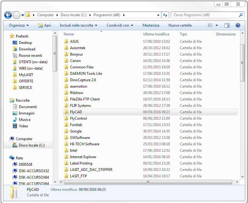
Problema di Font
Potrebbe essere un problema legato ai Font che il cliente utilizza.
In questo caso il passo correttivo da compiere è:
Andare nel percorso di installazione di FlyCAD, rinominare la cartella Fonts (assegnando un nome qualsiasi), disinstallare FlyCAD e successivamente reinstallarlo; dopo aver reinstallato FlyCAD provare manualmente uno alla volta i file VCF del cliente fino ad individuare il file che genera il problema.
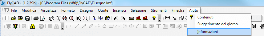
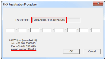
Nel caso in cui tu abbia sostituito il laser o il PC devi inserire il codice di ripristino nel software FlyCad, altrimenti il laser risulterà non collegato e sarà impossibile effettuare delle lavorazioni. In primo luogo assicurati che il laser sia acceso e che sia connesso al computer attraverso il cavo di rete. Apri FlyCad e seleziona dal menu Aiuto in alto la voce “Informazioni”

Questa modalità prevede l’utilizzo del laser senza comunicazione con FLYCAD.
Quando questa modalità è attiva è possibile inviare alcuni comandi all’unità LASER attraverso la porta seriale RS232 da un PLC oppure da un’applicazione appositamente concepita.