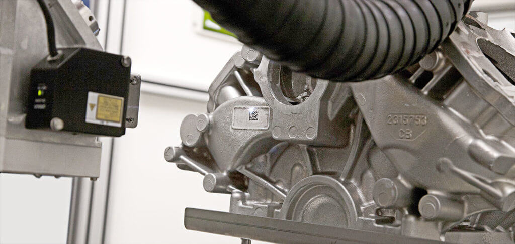
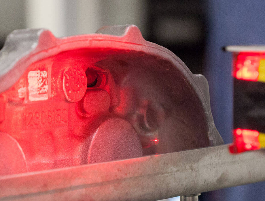
The shuttles do not require any specialization as it is the vision system that deals with objectification of the details to be marked, covering the whole area of the working field. Let’s examine the case in which the casting is incorrectly placed, not aligned or positioned beyond a limit angle: the machine generates an audible alarm and the shuttle leaves the cell so that the operator can reposition the piece.
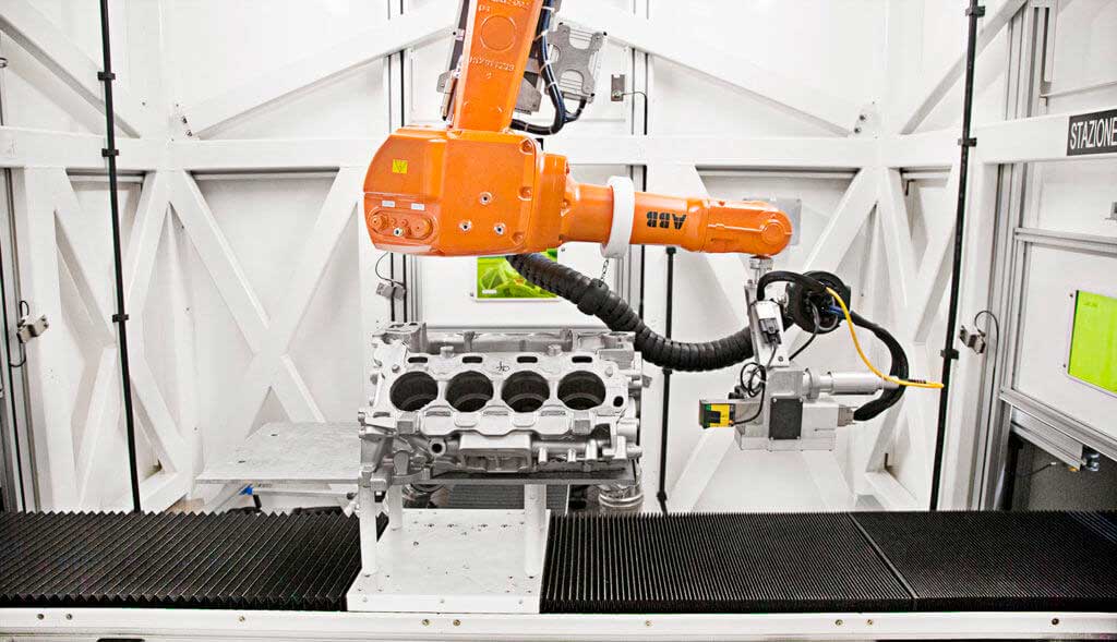
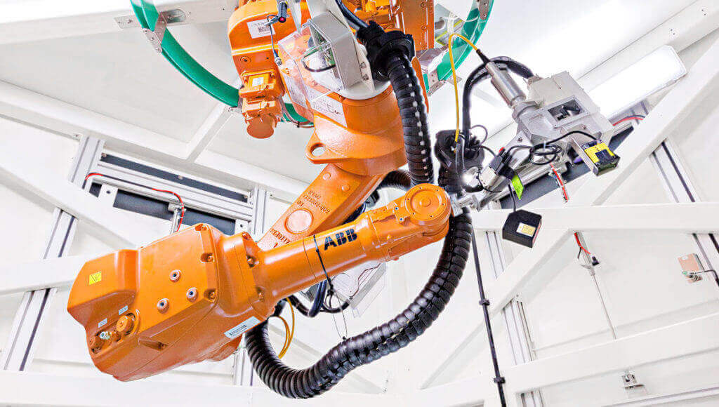
The machine, if connected to an SMTP server, can automatically forward an email to one or more pre-set addresses with specifications about the fault. The heart of this cell is naturally the six-axis robot, to which the 3D scanning head, the laser, the vision system and the distance meter are attached.