What is Dynamic-Z and how does it work?
One of the crucial aspects in the handling of a laser beam is the control of the focal point. This control can be achieved through the use of different optical lenses, allowing the beam to be adapted to the specific requirements of their applications.
Optical lenses are essential to the handling of a laser beam. They can converge or diverge the beam, directly influencing its focal point.
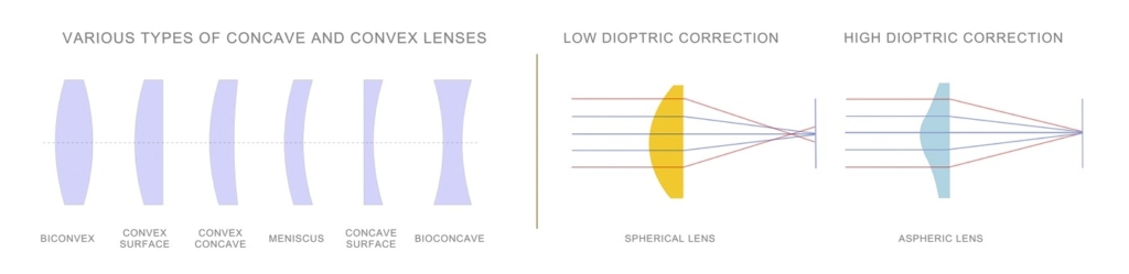
One of the most effective techniques to vary the focal point of a laser beam is the combination of different lenses such as concave or convex lenses.
Convex lenses are designed to converge the beam, while concave lenses have the opposite effect, defocusing the beam.
The fundamental law of refraction, stated by Snell, describes how light behaves when it passes through a medium with a different refractive index.

This law is essential for understanding how optical lenses can focus or defocus a laser beam.
When light passes through a converging lens, the beams will converge towards a focal point. Conversely, a diverging lens will cause the rays to diverge, simulating the origin from a virtual focal point.
The mathematical relationship associated with image formation through a lens emphasizes the relationship between Snell’s law and the optical properties of lenses:
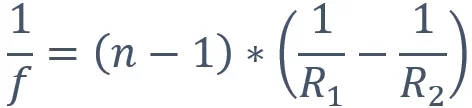
The combination of these lenses provides a synthesis of focal power, allowing for precise and adjustable focal points.
When there are three lenses in series, the total focal distance of the lens system can be calculated using the formula for the reciprocal sum of the focal distances.
This formula is given by:
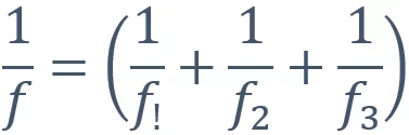
In more complex applications, lenses can be conveniently combined to allow for focus variations even over long distances.
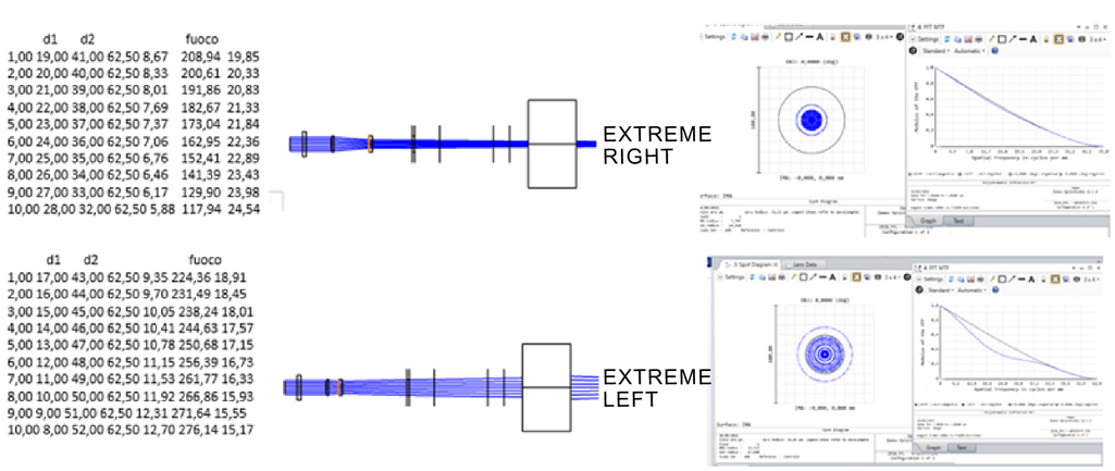
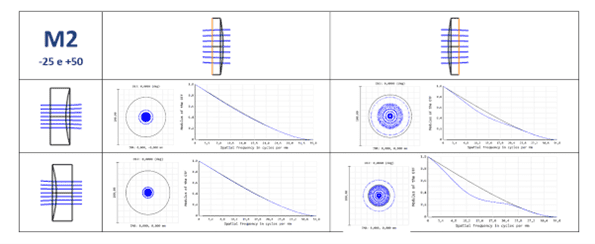
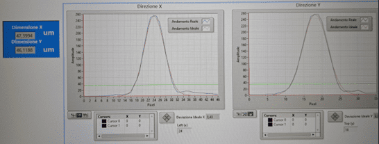
Parameters such as spot quality, shape, M2 and MTF are all crucial in assessing the effectiveness and reliability of a designed optical system. Optimization of these aspects is crucial in ensuring high-precision and consistent results in advanced laser applications.
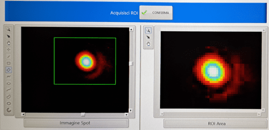
- Excellent spot quality is characterized by a smooth and concentrated intensity profile.
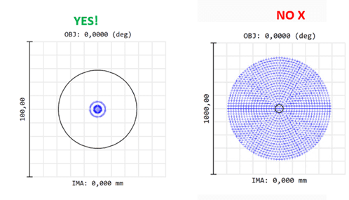
- The shape of the spot refers to the geometry of the area illuminated by the laser beam. In many applications, an attempt is made to obtain as symmetrical and uniform a spot as possible to ensure accurate results.
- In the vast world of optics and particle physics, the shape of laser spots plays a crucial role in practical applications, from industry to scientific research. These spots are often described with Gaussian distributions.
The Gaussian function, expressed mathematically as:
where A is the maximum amplitude, μ is the mean value and σ is the standard deviation, accurately describes the shape of the energy distributed in space.
The Gaussian histogram shape equation allows the value of f(x) to be calculated at any point in space, providing a complete mathematical description of the laser spot. Integration of the equation over the whole space provides the total energy.

Properties of the Gaussian curve are:
- Symmetry: The Gaussian is symmetric with respect to its mean value μ, which implies that the distribution is equal to the left and right of the peak.
- Area under the curve: The area under the Gaussian curve is proportional to the total energy of the spot.
- The M² parameter, or beam quality factor, is an indicator of the quality of a laser beam. It measures how far the beam profile deviates from that of an ideal Gaussian beam. An M² value of 1 indicates a perfectly Gaussian beam. Higher values indicate a deviation from the ideal pattern. The M² factor is especially relevant when considering beam propagation performance over long distances or when precise collimation is crucial.
- The modulated transfer function (MTF) is an indicator of an optical system’s ability to reproduce image details.
Limitations and solutions of 3D markings/engravings
Markings/engravings on three-dimensional solids can be realized within two limits:
The first limit is physical and is given by the inclination of the laser beam.
In fact, at perpendicularity, the laser beam is characterized by a spot of circular dimensions with the maximum amount of energy and consequently the maximum incisiveness on the material. Moving away from these perpendicularity conditions, the laser spot gradually becomes more and more elliptical, reducing the energy density and therefore the incisiveness on the material.

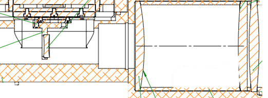
The second limit is mechanical and is given by the maximum possible travel of the Dynamic-Z.
This travel depends on the optical design used and generally takes on values of 35/40mm.
Depending on the case, these limits can sometimes be circumvented by using, for example, a marking/engraving chuck on entire cylindrical surfaces:

Wrapping and Projection and Example of 3D Marking
We have developed technologies that allow us to mark or engrave on complex surfaces with very high geometric precision.
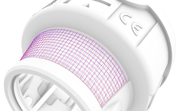
In fact, in addition to the simple planar projection, we are able to wrap any flat graphic on any three-dimensional solid, thus obtaining results that are geometrically extremely faithful to what was foreseen in the design phase, thus realizing markings/engravings in which geometric distortions are absent.
This type of complex marking/engraving is made possible by the co-existence of two different technologies:
- Wrapping 3D à Which allows us to mark geometrically perfect three-dimensional designs.
- Dynamic-Z à Which allows us to maintain focus on all points of the surface under examination.
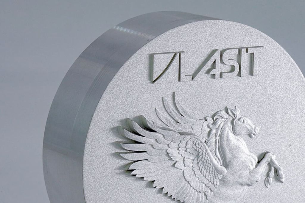
Below are some examples of 3D marking:
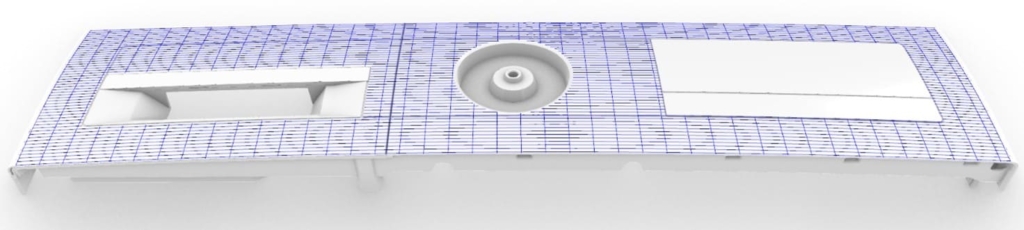
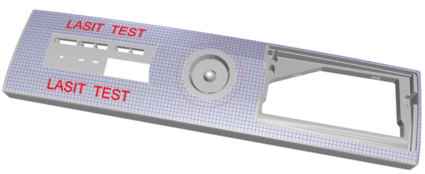


Comparative examples of projection and wrapping of a grid on a truncated cone surface:

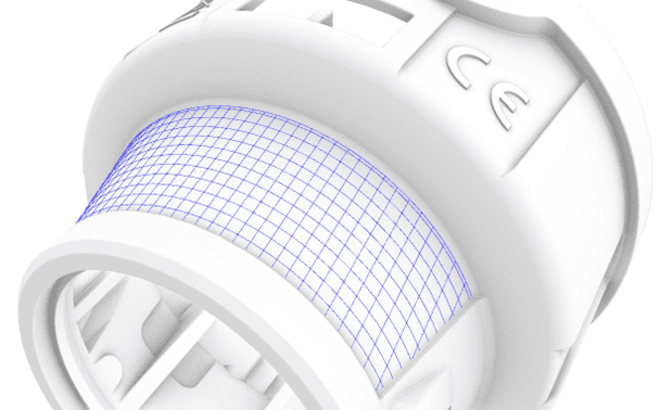
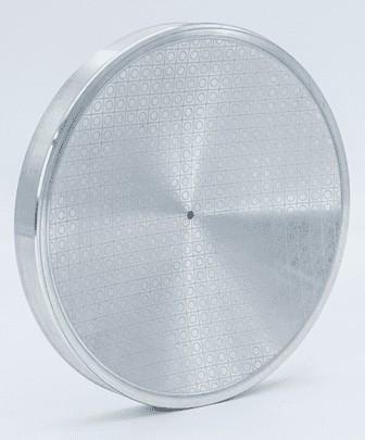
Example of marking on a hemispherical surface:
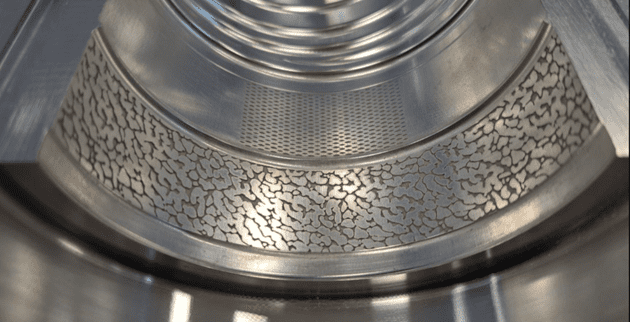
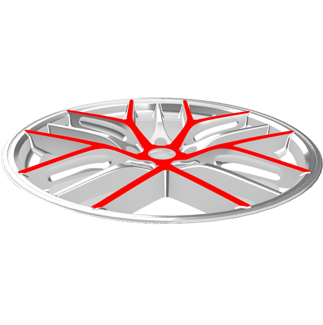
Example of 3D de-painting on a car rim:

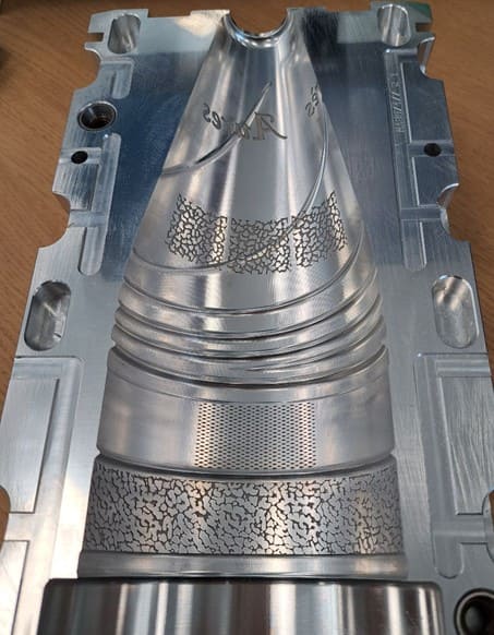
Example of 3D engraving of textures and lettering inside a bottle mold:
3-Axis head for 3D marking: When to use it?
Considering that a three-axis scanning head has a higher cost than the traditional two-axis system, it is important to understand when its use is actually worthwhile.
As mentioned above, the essential difference between the two systems relates to the different focal tolerance, or rather to the possibility of marking a detail which, due to its geometrical characteristics, is not always at the same distance of focus with respect to the edge of the scanning head.
Considering a 100×100 mm marking area, a three-axis head usually has a focusing tolerance of about 40mm, while the traditional head is limited to a tolerance between two 2mm and 6mm. It goes without saying that larger marking areas have a larger focusing tolerance.