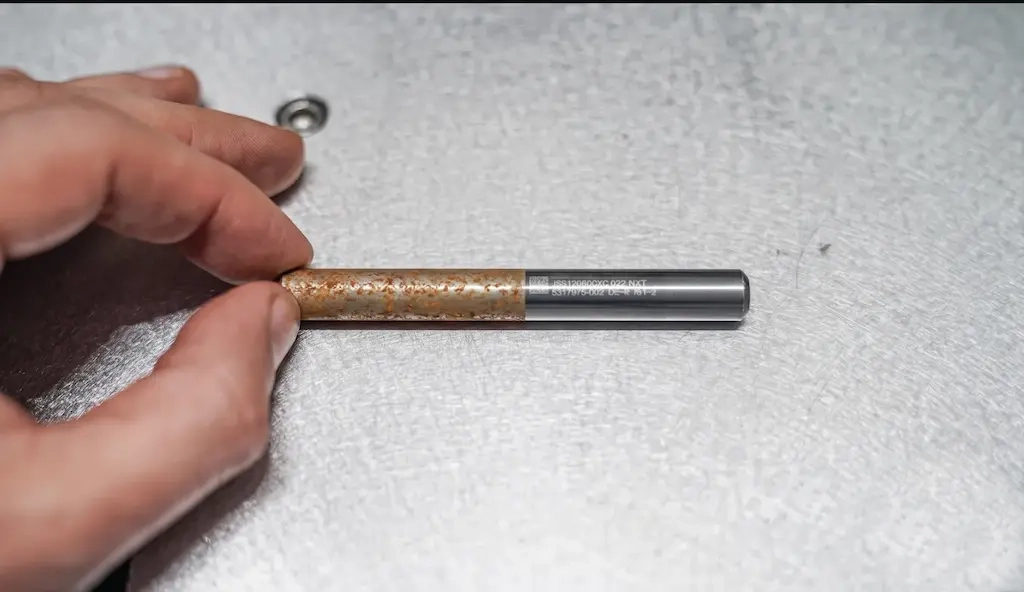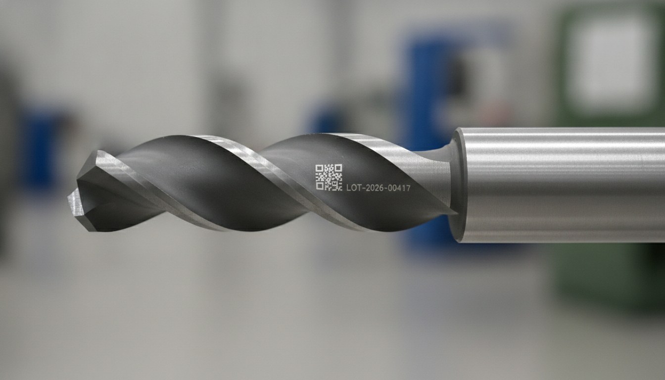
Anyone who produces cutting tools, milling cutters, drill bits, taps, and dies knows the last operation of the cycle well: marking codes, logos, batches, and serials for traceability. On these components, however, marking comes when the part has already been hardened — often over 60 HRC, with high-speed steels reaching 62-66 HRC — and in many cases it is also coated with a PVD layer of titanium nitride (TiN) or similar coatings. These are the conditions in which the concentrated energy of a laser beam meets the most delicate material it can find.
The problem is that a marking can pass the readability check and, at the same time, have introduced an invisible defect beneath the surface. Poorly controlled heat input on a martensitic steel causes local tempering, residual stresses, and, in the worst cases, microcracks that start right at the edge of the characters. On a tool that works under fatigue, with cyclic loads and stressed cutting edges, that point becomes a trigger.
For this reason, on hardened and coated steels the quality criterion cannot stop at the readability of the code: it must include the metallurgical integrity of the marked area. And integrity is governed with two concrete levers — the process parameters and the position of the marking on the part.
Why hardened steel is fragile to concentrated energy
Hardening gives steel its hardness by transforming its structure into martensite, a hard but metastable phase. It is precisely this metastability that makes it sensitive to heat: it is enough to locally heat the material above its tempering temperature for the martensite to transform, with a limited but real loss of hardness in the heat-affected zone.
When the beam energy is concentrated in short times and small areas, the thermal gradient between the point struck and the surrounding material is steep. The rapid cooling that follows leaves tensile residual stresses, the most dangerous kind, because by adding to the operating loads they lower the crack-initiation threshold. On very hard steels, naturally low in toughness, the margin is thin: the same property that makes the tool wear-resistant makes it poorly tolerant of localized stresses.
This is why marking on hardened steel requires a different logic from that used on a mild steel or an annealed stainless: it is not about “writing more,” but about delivering the least possible energy to the material to achieve the necessary contrast.
The PVD/TiN coating: a few microns that change everything
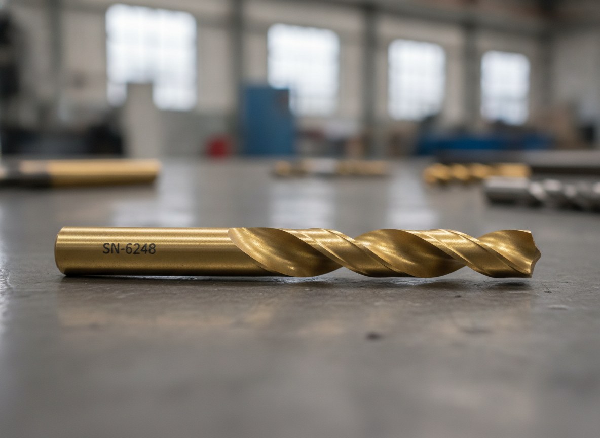
PVD coatings such as titanium nitride have thicknesses on the order of a few microns and a hardness higher than that of the substrate. They are designed to reduce friction and wear of the cutting edge, not to withstand a localized thermal shock. Too energetic a pulse can burn the coating, alter its color at the edges of the marking or, worse, trigger its local delamination — the detachment of the layer from the substrate.
On coated tools there are two legitimate approaches. Contrast can be achieved by acting with very low energy directly on the layer, modifying its optical rendering without removing it; or the coating can be removed in a controlled way at the characters, exploiting the contrast between layer and substrate. In both cases the key word is control: the process window over a few microns is narrow, and it must be found on the real coating, not on a nominal sample.
Low fluence and multiple passes: distributing the energy
The strategy that protects metallurgical integrity is counterintuitive compared to the instinct to “push” the power: you work at low fluence, that is, with little energy per unit of surface at each pulse, and you build the marking with several light passes instead of a single intense pass. The total energy needed for contrast is thus diluted over time, giving the heat the chance to dissipate between one pass and the next and reducing the thermal peak that triggers tempering.
Fluence per pass Heat-affected zone Low fluence, multiple passesThis approach relies on the nature of the source. MOPA sources, with adjustable pulse duration, allow you to choose short pulses that heat the material less; the 1064 nm fiber remains the reference for metals, while ultrashort-pulse sources in the picosecond range bring heat input to a negligible level, ideal where the heat-affected zone must be kept to a minimum. The relationship between power, pulse duration, and effect on the material is the heart of the matter: it is worth exploring in detail in laser power and pulse duration.
Annealing or ablation: two ways to create contrast, two thermal balances
On steel, dark annealing marking comes from a controlled surface oxidation: it does not remove material, but by definition it introduces heat, and it is therefore the mode that requires the most attention on hardened steel. Low-fluence ablation, on the contrary, acts on a minimal thickness of surface with short pulses, limiting the bulk heat input but generating a slight topography.
| Aspect | Annealing (oxidation) | Low-fluence ablation |
|---|---|---|
| Material removal | None | Minimal surface layer |
| Local heat input | Higher | Contained with short pulses |
| Effect on PVD/TiN coating | Risk of color alteration | Risk of delamination if energy is high |
| Contrast obtained | Dark tone from oxidation | Surface topography |
There is no absolutely right choice: it depends on the hardness, on the presence and type of coating, on the need for a low-relief code or a surface that stays intact to the touch. The practical rule is to verify the real effect with a metallographic cross-section and a microhardness measurement in the marked area, rather than relying on the visual appearance of the code.
Where you can mark and where you can’t: reading the tool geometry
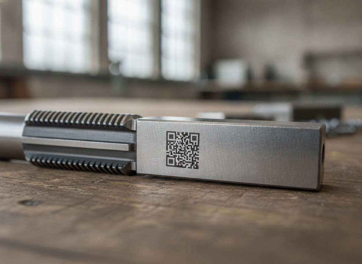
The position of the marking is a lever of integrity just as much as the parameters. On a tool there are zones where a slight surface alteration is irrelevant and zones where it is unacceptable. The shank, the non-functional flat faces, and the unstressed portions of the body are the natural areas for codes and serials. The cutting edges, the fillet radii, the flutes, and any surface subject to load or stress concentration should instead be avoided: that is where a microcrack or a residual stress finds the worst trigger.
This also applies to marking milling cutters and cutting tools, where the temptation to place the code in the most convenient area for loading must be balanced against the stress map of the part. It is a decision that rarely rests with the machine operator alone: it involves the functional geometry of the tool.
How to validate marking on hardened steel
On these materials, validation is not a formality. Before putting a cycle into production, it makes sense to mark real samples — same steel, same hardness, same coating — and take them to the lab for a check that goes beyond reading the code: a metallographic cross-section to observe the heat-affected zone, a microhardness measurement to quantify any tempering, and an in-line check of readability and code grading. It is the only way to know whether the chosen process window truly protects the integrity of the part.
When it makes sense, and when to agree on the position with the engineering department
Low-fluence laser marking is the most rational choice when hardened and coated tools need to be traced permanently, without the mechanical triggers of stamping or dot peening and without consumables. On very hard steels and on PVD coatings it is often the only way to obtain a permanent code without compromising the function of the part.
It is not, however, a decision to make by isolating the marking alone. When the component works under fatigue, when the safety margins are tight, or when the available surface forces you to move close to a cutting edge or a critical radius, the position and the mode must be agreed upon with the engineering department and with those who know the stress map. In those cases the question is no longer “is the code readable?” but “where and how can we mark without shortening the tool’s life?” It is the same reasoning that guides the choice of a laser marker for a machine shop: the technology serves the process, not the other way around.

Applications Manager | LASIT
Applications Manager at LASIT for over 20 years, Mario Palmieri oversees the management and development of the company’s laser laboratory. He is responsible for conducting sample tests for customers, supporting the automotive, medical, aerospace and electronics sectors in identifying the most suitable laser marking solution for their needs.