Introduction: glass
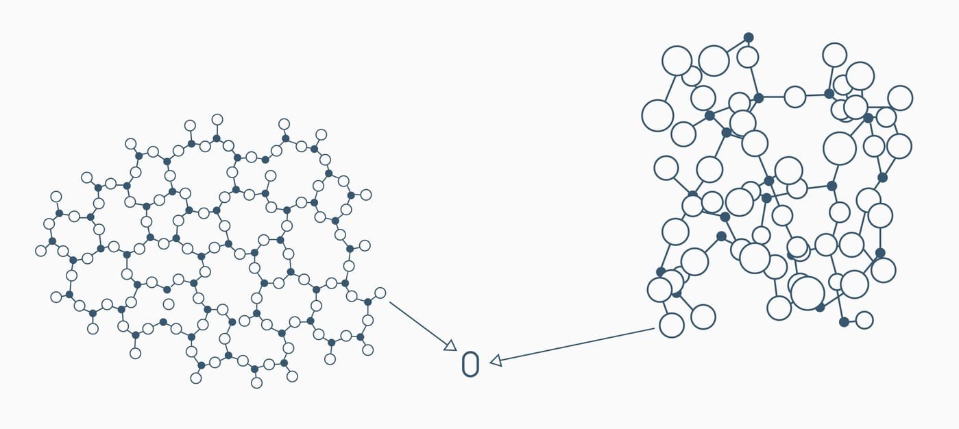
Glass is a material of natural origin, comprised primarily of silica (SiO2). It’s an amorphous solid: its atoms are as rigid as in a crystal but as disordered as in a liquid. Therefore, they can be likened to highly viscous supercooled liquids.
Most of the glass available on the market isn’t composed solely of silica. Other components are added to silica to modify the material’s properties and make it suitable for different uses.
However, adding substances to glass alters its ‘laserability.’
Due to its more consistent structure, industrial glass is a superior choice for laser applications. On the other hand, artisanal glass is more difficult to use with lasers. In this case, artisanal processing may result in variations in composition and structure, including microfractures. When subjected to the heat of a laser, these microfractures can cause the glass to crack.
Glass made entirely from natural substances possesses exceptional intrinsic characteristics, including transparency, density, structural uniformity, chemical and biological resistance, impermeability to liquids, gases, vapors, and microorganisms, durability, sterilizability, and ecological compatibility as it can be recycled for infinite number of times.
However, glass has a low tolerance for thermal expansion. Laser applied to glass generates microscopic cracks, resulting in markings or cuts.
Depending on the type of glass, markings can be made in different ways.
- Soda Glass:
Soda glass is the most common type of glass, primarily used for windows, bottles, glass flatware, and other everyday objects. It is preferred for laser technology applications.
On this type of glass, markings are made by generating thousands of microfractures on its surface. Thermal shock expands soda glass, causing microscopic fractures because of its inherent rigidity. The outcome is an opaque marking with a satin finish like those obtained with traditional methods but at a much lower price.
This process is evident in various applications, including decorative work on glassware and flatware, as well as windows and cabinets. It’s also used in the automotive industry for marking identification codes on windshields and windows and for manufacturing laboratory glassware with measurement markings.
- Quartz Glass
Quartz glass is obtained by fusing quartz instead of silica. It stands out for its high resistance to heat and corrosion and great optic transmissibility.
CO2 laser markings on quartz glass are done through superficial fusion. The fusion of the material alters the glass’s lattice structure, causing light to refract differently through the markings compared to the surrounding surface.
- Boro-Silicate Glass
Borosilicate glass, or Pyrex, is obtained by adding minerals, such as boron and other compounds, to silica. The resulting chemical reaction produces glass that is highly resistant to thermal expansion. That’s why it’s used for flatware and oven trays. Borosilicate glass can undergo CO2 laser markings.
Advantages of Laser Technology for Glass over Other Methods.
Laser glass engraving is a highly efficient and economically convenient process for small-scale and mass production.
This type of engraving:
- Resists wear, corrosion, and aggressive substances, such as concentrated or acid detergents.
- Ensures limited costs because no consumables (e.g., sprays, inks, pastes, etc.) are involved.
- Ensures speed, even during format changes: you can mark different products without downtime.
- Ensures high definition, even for miniature markings.
Compared to sandblasting on glass or mechanical engraving:
- Laser engraving has no design limitations. Sandblasting is not as accurate as laser engraving and cannot create thin details.
- It’s a faster process: sandblasting takes longer than laser engraving.
Type of lasers: UV, CO2, and Picosecond
The interaction between lasers and glass is influenced by the laser’s wavelength and pulse duration. The picosecond laser is ideal for high-precision applications.
Glass and Picosecond Laser
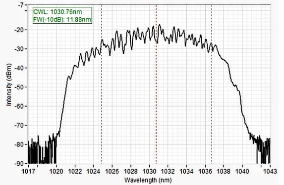
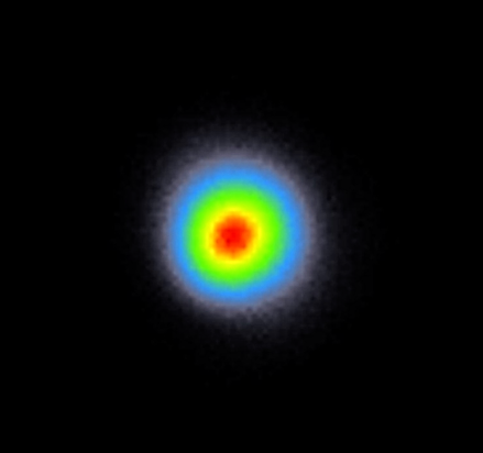
Picosecond laser emits ultra-short pulses with a duration of picoseconds.
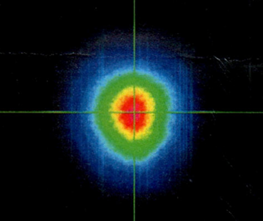
It has a wavelength of 1030 nm and a spot circularity of over 96%. Every pulse lasts about 1.9 ps, and the maximum energy reaches 26.4 μJ. In “burst” mode, it provides high-energy pulses (over 230-250 μJ at 200kHz).
When these pulses hit the glass, the energy concentrated in such a short time intensely interacts with the material.
The laser energy is powerful enough to disrupt chemical bonds in glass, resulting in small cavities or cuts.
Unlike lasers with longer wavelengths, picosecond lasers minimally heat the surrounding material since the energy is concentrated in a short period of time. The result is a reduced risk of thermal damage to the glass. That’s why picosecond lasers are ideal for marking and precision machining applications.
Glass and Co2 laser
CO2 lasers emit radiation at a wavelength of 10,600 nanometers with a circularity exceeding 90% in the far-infrared region. When this radiation hits the glass, it’s absorbed by the material, heating the surface. The interaction between the CO2 laser and the glass can result in the following:
Fusion and Ablation: Because of the high temperatures reached, the glass may melt or ablate from the surface. That’s why CO2 lasers are ideal for cutting and engraving glass. However, it can lack precision compared to picosecond lasers in terms of machining details.
Increased heat propagation: CO2 lasers cause greater heat propagation compared to picosecond lasers, potentially raising the risk of cracks or thermal damage.
Glass and UV laser
UV lasers have a circularity of more than 98% and operate at shorter wavelengths, usually between 100 and 400 nm. When this radiation hits the glass, it can cause photoablation phenomena like those caused by picosecond lasers but on a coarser scale.
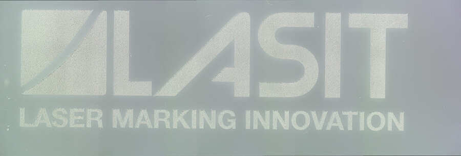
Experimental Tests Comparing UV, PICO, and CO2
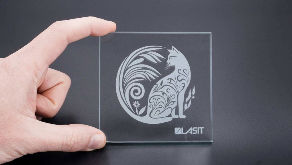
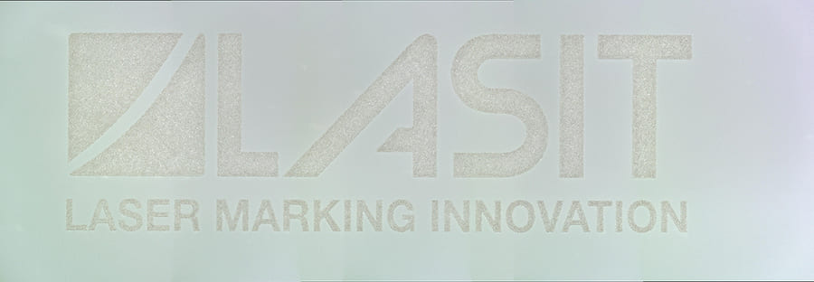
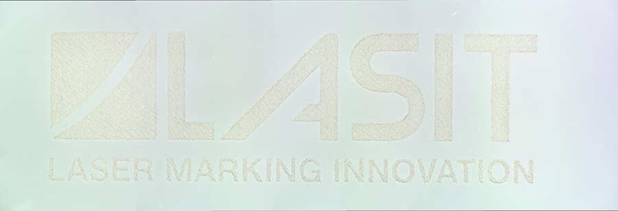
Tests were conducted by marking Lasit’s logo on the glass, using the optimal marking parameters for each optical system or source.
The types of sources used are the following: CO2, UV, and Fiber (Pico with burst mode).
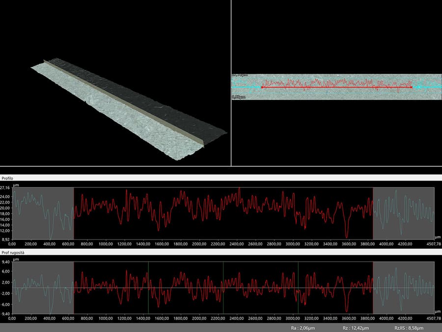
The measurements taken and images captured were obtained by using a parfocal microscope:
The 4k Microscope allows the three-dimensional profile of the marking to be visualized with zoom levels ranging between 20x and 2500x.
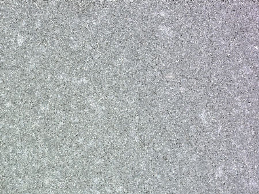
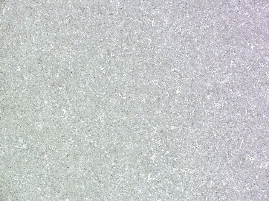
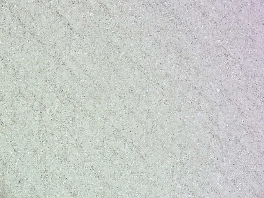
CO2
Surface marking
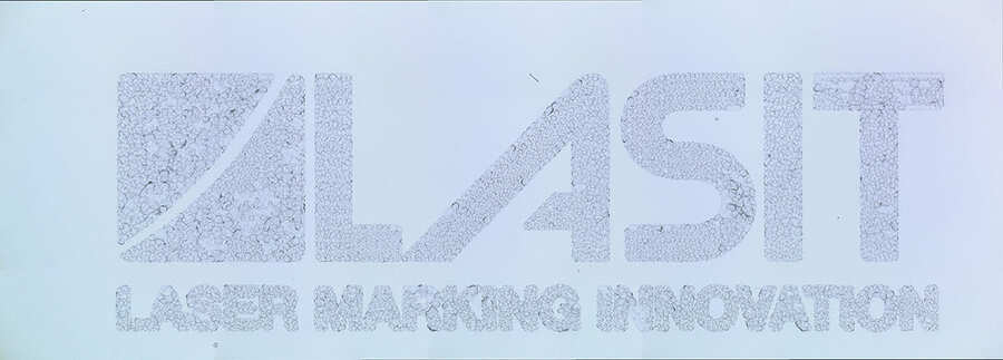
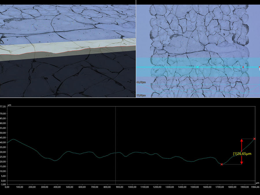

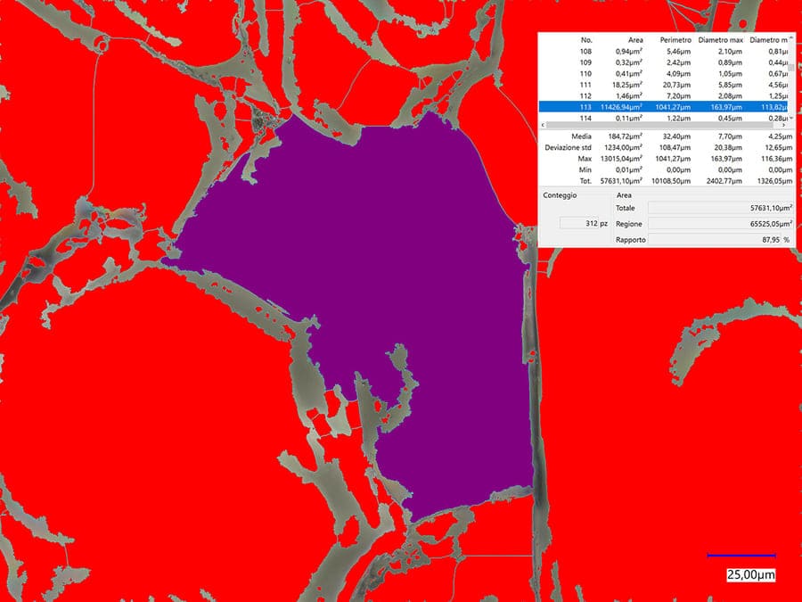
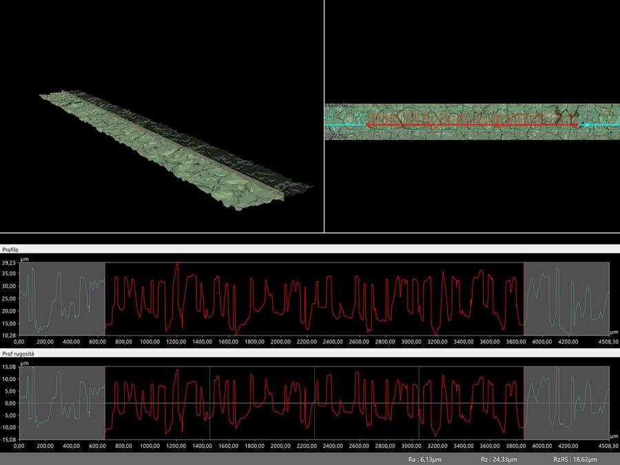
Results of CO2 laser testing
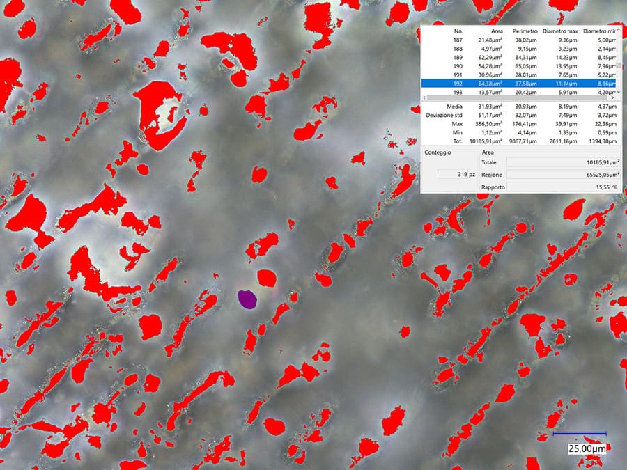
The CO2 source results in a less defined yet highly rough marking, with Ra=6μm and Rz=24μm.
In particular, smaller details are hardly visible. Therefore, this type of source is not recommended for marking small and miniature details.
This result is due to the larger laser spot size and the presence of large grains (approximately 11,500 μm²) on the machined surface.
That’s also why marking inside the material is not possible.
This type of marking offers the advantages of a wide working range, increased depth of field, and reduced marking time.
| Properties | Result (1 is worst, 3 is best) |
| Marking definition | ☆ |
| Surface finish | ☆ |
| Size of the laser spot | ☆ |
| Grain size | ☆ |
| Depth of field | ☆ ☆ ☆ |
| Size of the Marking Plane | ☆ ☆ ☆ |
| Marking Time | ☆ ☆ ☆ |
| White markings inside the material | NO |
| Dark markings inside the material | NO |
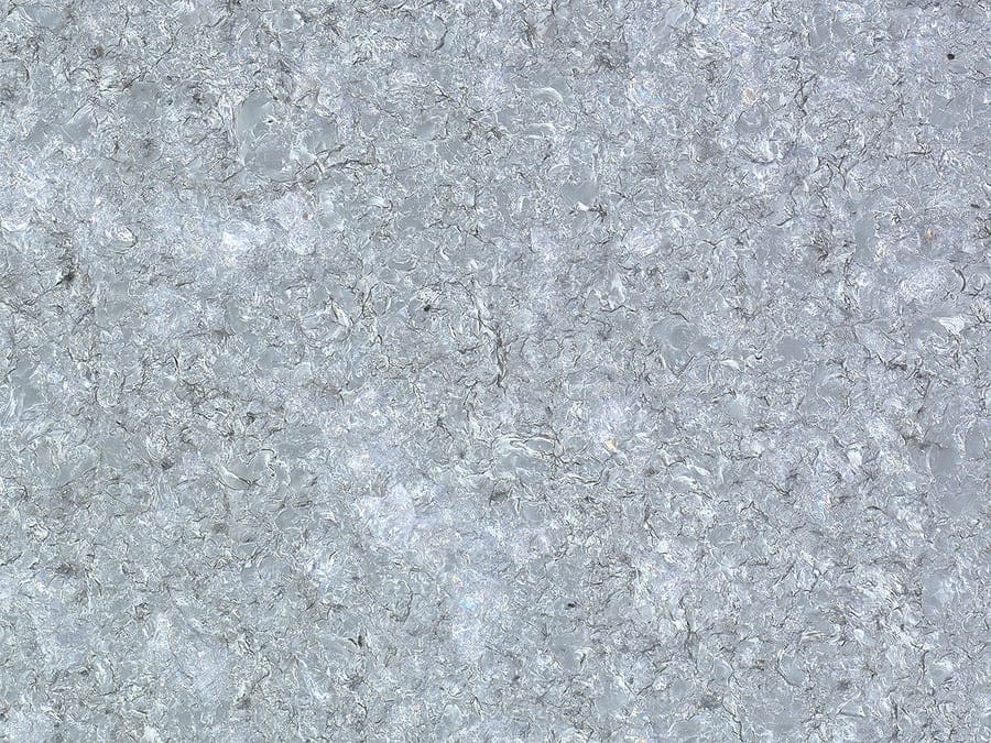
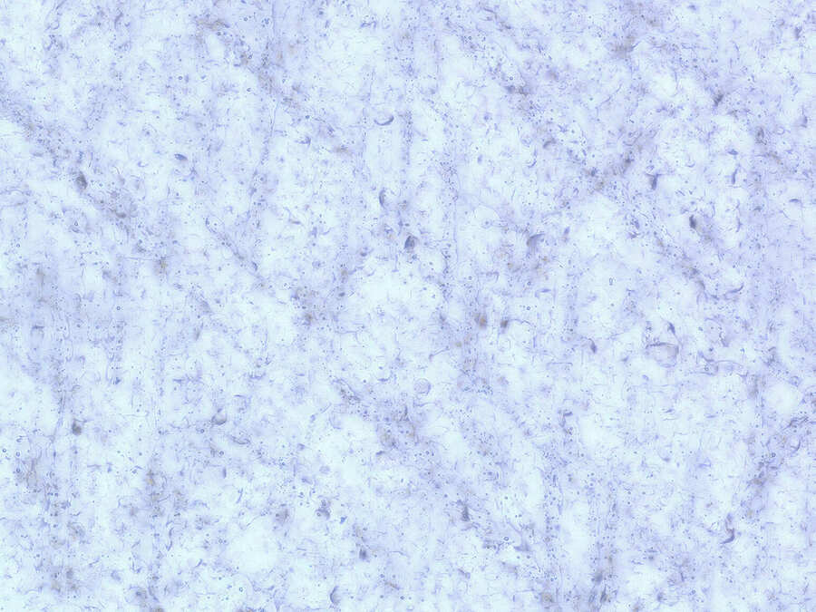
UV
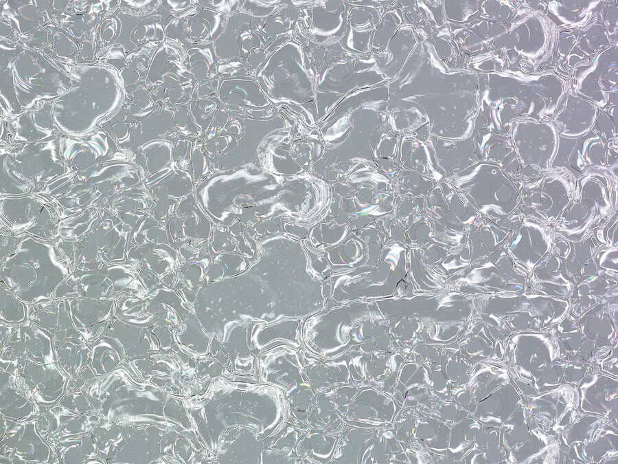
Surface marking

Marcatura interna
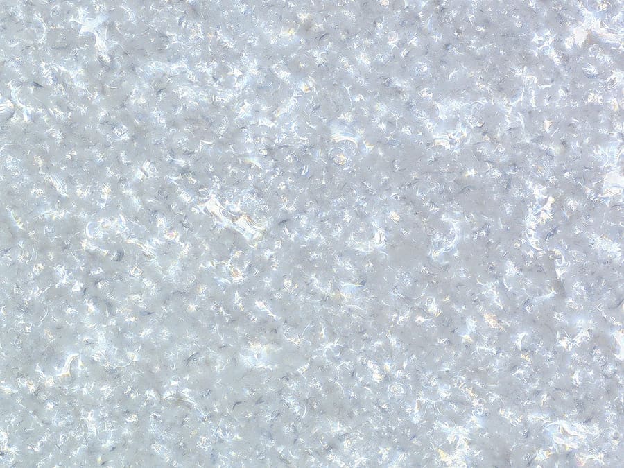
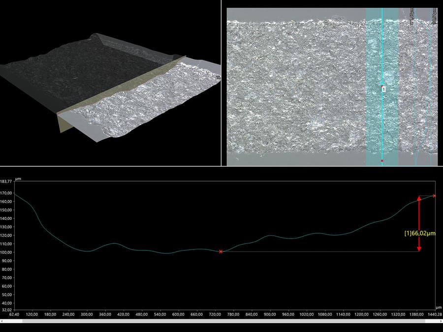
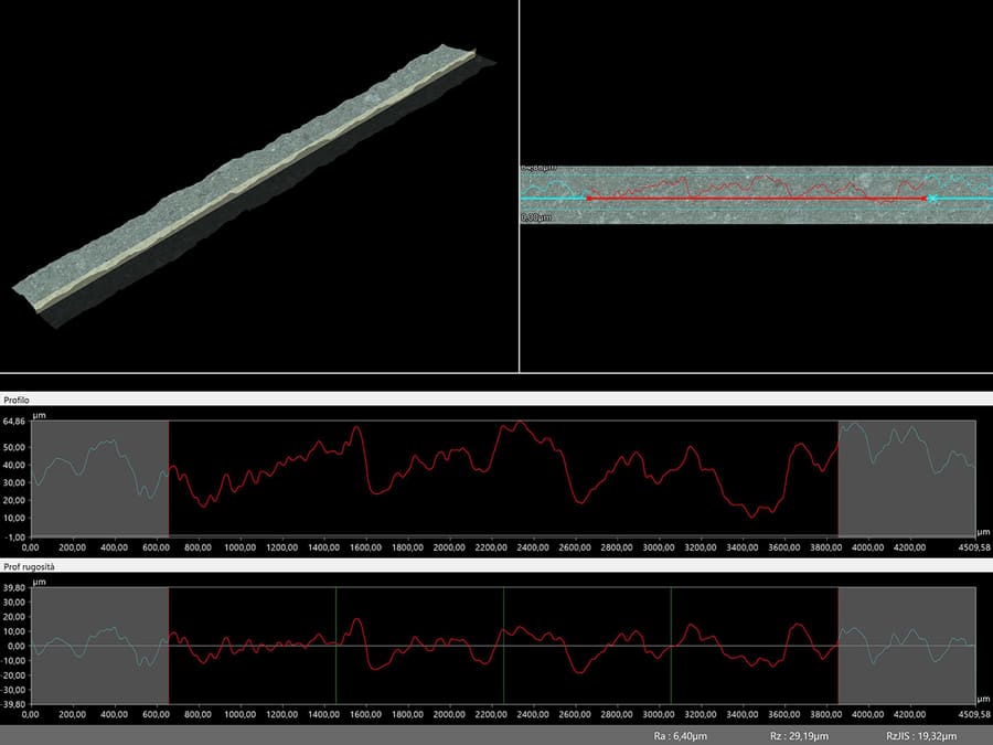
Results of UV laser testing
The UV source results in a defined and highly rough marking, with Ra=6μm and Rz=26μm.
In particular, smaller details are highly visible. Therefore, this type of source is suitable for marking small and miniature details.
This result is possible thanks to a smaller laser spot and even grain size on the machined surface.
A deeper pronounced profile is typically seen (in tests up to 66um) due to the material’s high reactivity with this kind of source.
Moreover, this type of source allows for well-defined and even markings inside the material.
This type of marking offers the advantages of a wide working range and increased depth of field.
| Properties | Result (1 is worst, 3 is best) |
| Marking definition | ☆☆ |
| Surface finish | ☆ |
| Size of the laser spot | ☆ |
| Grain size | ☆☆ |
| Depth of field | ☆ ☆ ☆ |
| Size of the Marking Plane | ☆ ☆ ☆ |
| Marking Time | ☆ ☆ |
| White markings inside the material | ☆ ☆ |
| Dark markings inside the material | NO |
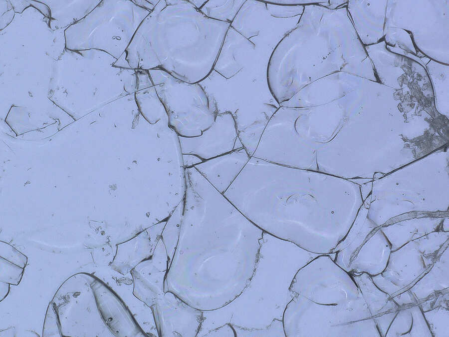
PICO – SURFACE MARKING
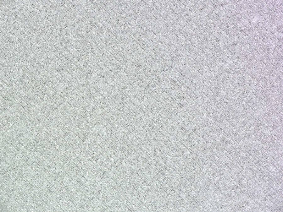
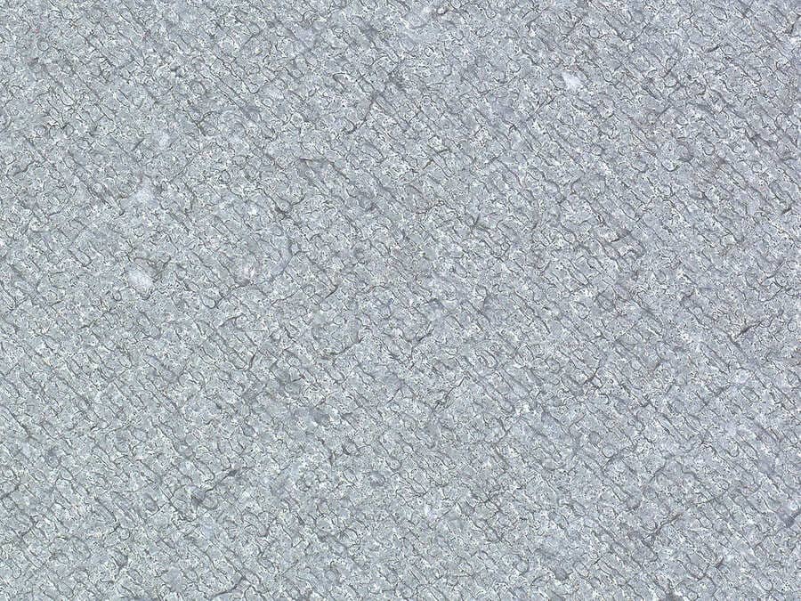
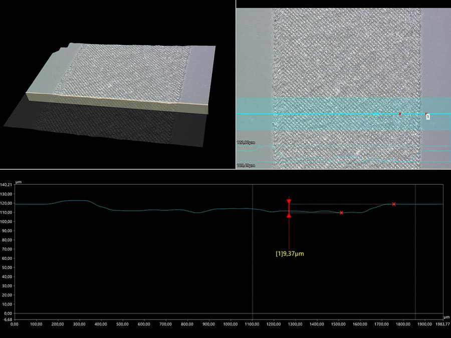

Results of pico burst laser testing
The Fiber source with picosecond pulses results in a highly defined and low rough marking, with Ra=6μm and Rz=26μm.
In particular, smaller details are highly visible. Therefore, this type of source is recommended for marking small and miniature details.
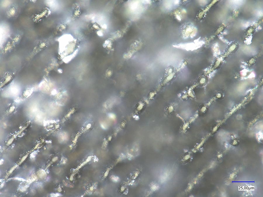
This result is possible thanks to a smaller laser spot, low contact time with the material, and even grain size (60 um2) on the machined surface.
Being in the order of picoseconds, the entire energy is used to machine the surface, limiting heat dissipation within the material. That’s why the profile’s depth is low (10um), being limited to the machined surface.
Moreover, the burst function allows for the creation of well-defined and consistent markings in two colors (light and dark) inside the material.
However, this type of marking has the disadvantage of having a reduced working range and depth of field.
| Properties | Result (1 is worst, 3 is best) |
| Marking definition | ☆ ☆ ☆ |
| Surface finish | ☆ ☆ ☆ |
| Size of the laser spot | ☆ ☆ ☆ |
| Grain size | ☆ ☆ ☆ |
| Depth of field | ☆ |
| Size of the Marking Plane | ☆ |
| Marking Time | ☆ ☆ |
| White markings inside the material | ☆ ☆ ☆ |
| Dark markings inside the material | ☆ ☆ ☆ |
Comparing results:
| Properties | CO2 results | UV results | PICO results |
| Marking quality | ☆ | ☆☆ | ☆ ☆ ☆ |
| Surface finish | ☆ | ☆ | ☆ ☆ ☆ |
| Spot size | ☆ | ☆ ☆ | ☆ ☆ ☆ |
| Grain size | ☆ | ☆ ☆ | ☆ ☆ ☆ |
| Depth of field | ☆ ☆ | ☆ ☆ ☆ | ☆ |
| Size of the Marking Plane | ☆ ☆ | ☆ ☆ ☆ | ☆ |
| Marking Time | ☆ ☆ ☆ | ☆ ☆ | ☆ ☆ |
| White markings inside the material | NO | ☆ ☆ | ☆ ☆ ☆ |
| Dark markings inside the material | NO | NO | ☆ ☆ ☆ |