The LASIT software package for checking the marker includes:
• The control software that includes a CAD environment for the creation of the workings and their realization, FlyCAD.
• The software for the maintenance of the FLyControl system.
The system is normally supplied with the installed software. If there is a need to reinstall one or more components of the software package, follow the procedures described below.
To download the latest version of FlyControl go here
To start the installation, ask for the password via chat or email.
Pre-purchased for the installation of FlyCad
The FlyControl software must be installed and it must be started at least once and properly configured – if you have not installed FlyControl see the previous paragraph.
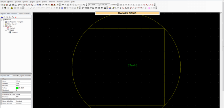
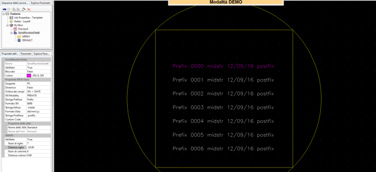
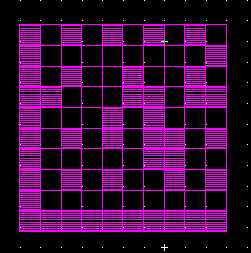
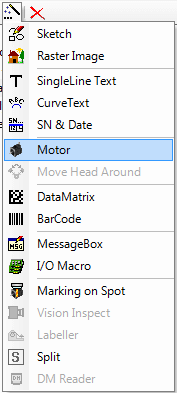
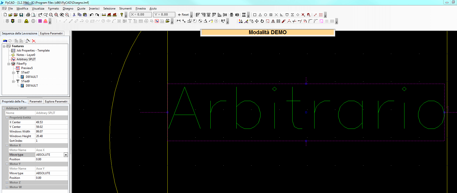
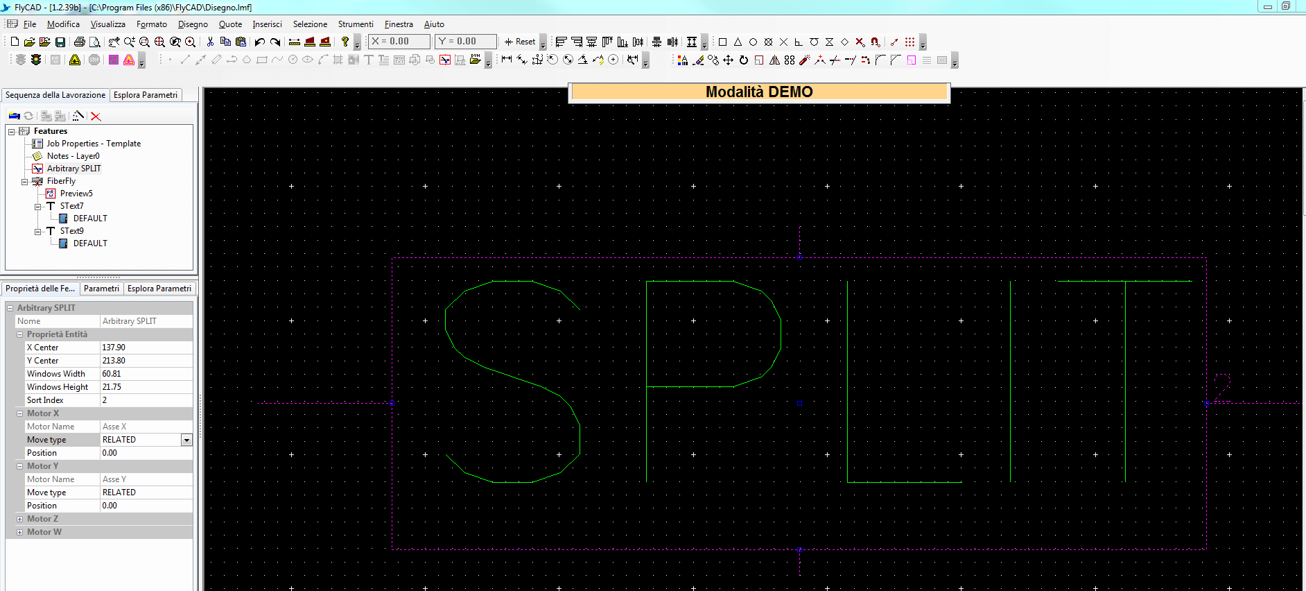
The Preview is a tool which displays on the marking area where the marking process will be accomplished, so consequently it shows where to place the parts to be marked. The marking system uses a low power infrared laser (class II laser) which is not dangerous in order to show the drawing to be marked.
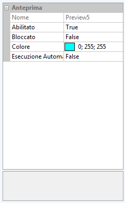
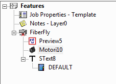
Preview Properties
Where is the preview?
Preview is displayed as a default for each new drawing in the jobs’ tree on the left, as shown in the picture below.

Which kind of forms or shapes can I draw?
The Preview can be employed to draw lines, rectangles, polylines, polygons, squares, circles. You can select each one of these forms from the Draw bar (see picture below) which is on the top the page.

NB When FlyCad is launched for the first time, the Draw bar is situated vertically on the right side of the page. It can be moved and put where it can be more useful.
To learn more about FlyCad toolbars please see the video you may find here
______________________
Where are they located and what are the features of the Preview?
Once you have selected the Preview from the jobs’ tree, a window with three buttons will be displayed. If you click on the first one you will see the Preview properties, as shown in the picture below.
The first property allows for enabling/disabling the selected object by clicking either on TRUE or FALSE. Once disabled, the object disappears from the CAD drawing place but it will be saved in the job tree and it could be used in a second time
The second property locks/unlocks the object (to modify a locked object you must unlock it). Once you lock an object, it will be always visible on the CAD drawing plan but it could not be selected and all actions will not interfere with its position nor with its characteristics
The third property allows for changing the color of the displayed objects
The last property permits to set the automatic preview, which means enabling it every time a new drawing is loaded

Shape Preview
FlyCad parameters test is a very useful tool which helps the operator in the choice of the marking parameters.
If you have to mark for the first time an object and you do not know the result you would like to obtain, instead of marking several times the same thing you can run a parameters test.
Follow the steps below.
Let us draw as an example a square. Select it and click on the Hatch icon in the toolbar to fill it. Select then the pattern from the menu.

Once marked you will see all the results, so you can choose which one fulfils your requirements.
Please watch the video you will find here if you want to see the procedure in details.
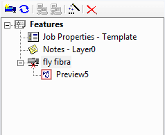
All the types of graphic files can be imported, also PDFs. It is really important though that those files had been created with a vector program.
If you have an image (Jpg, etc…) saved as PDF, it will not be loaded.
Creating a Drawing
How to create a draw
To manually draw whatever kind of shape you firstly need to create a sketch. In the jobs’ tree on the left select the magic wand icon and click on “Sketch”


Properties Text FlyCad
Writing a text

A new text will appear with a default name, SText# (where # stands for a progressive number).
Selecting the text node you can see its properties in the “Feature properties” box, which is below the job tree.

The default string is composed by:

Properties
String codification table

SN % Date Properties
To modify the properties of the serial number and date click on “Feature properties” in the window below the jobs’ tree.


_________________________________
Export marked Sn in excel
You can export a list of serial numbers to Excel using FlyCad.


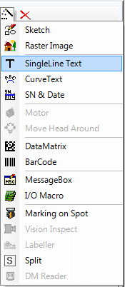
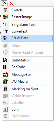
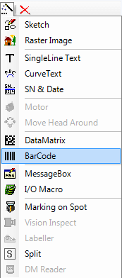
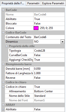
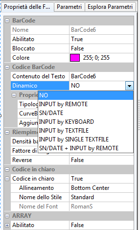
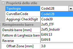
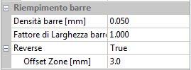
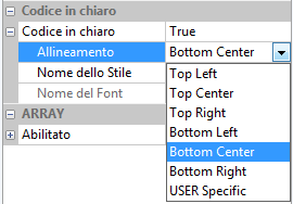
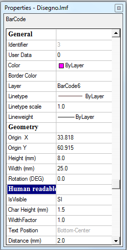
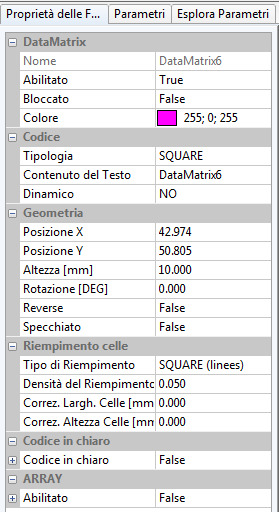
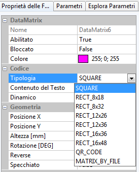
Once selected, you can access to the BarCode properties by clicking on Feature properties below the jobs’tree.
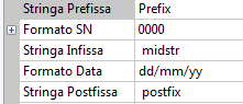
Properties Barcode


As you can see, you can choose between:
3. In the “Style Properties” section you can choose the type of code you prefer (Code 128, Code 39, 2of5_ITF, 2of5_Industr, EAN 13 o EAN 8), you can make it curved or you can add the CheckDigit (a redundancy check used for error detection)

4. In the “Bars Filling” section you can change the parameters relating to the bar density, the bars width factor, or you can enable the Reverse which inverts the marking tonality according to the material, creating an Offset zone (which can be modified) in order to improve readability in marking.

5. You can choose to display the barcode data as an alphanumerical code, that is to say a text which is human readable in case of problems in the automatic reading devices: you just have to enable the Human Readable Text function et set the alignment and the style you prefer. You can do this even selecting the barcode and right-clicking on it, choosing the “Properties” voice.


Please refer yourself to How to modify a text and How to create a new text style in the specific section about the creation of a text.
6. Enabling the ARRAY function you can personalize the barcode organizing more strings in a matrix.
You can choose the number of rows and columns but also the distance between them.


Properties
How many characters can a datamatrix encode?
In theory speaking, a squared DataMatrix can encode up to 3116 numbers o 2335 alphanumerical characters in an area of 144×144=20736 cells.
Rectangular DataMatrix contain much less characters. The limit is 98 numbers or 72 characters for a matrix of 16×48 (rows/columns).
Properties of Datamatrix
Once selected, in the window below the jobs’ tree you can modify the properties of the DataMatrix in the Feature properties window.


QR Codes (Quick Response Codes) use an encoding system like DataMatrix but they are more employed in the consumer world than the industrial system because they are normally designed to be read by a smartphone.


PROPERTIES
PLANE


To use the CYLINDER split you need a W rotary axis. This modality allows you to mark cylindrical parts, dividing into little pieces the circumference (C = 2 π r) and marking them one at a time on the part, employing W axis rotary movement.
Selecting this function you will get this window:

Insert the cylinder diameter of the piece but do not modify neither the conical factor nor the Window PosX.
Set the Split X dimension like the standard marking field (in this case we put 100 because we have a F160 focal lens).
Split Y dimension instead represents the little slice of circumference that the laser will mark at once (the bigger the slice the faster the marking process). We set 2mm for convenience but it is clear that you can insert any value depending on the part to mark.
The object to mark has to be placed precisely in the center of the marking area, rotated of 90°. In this example we have written a SingleLine text.

The last step consists of inserting a motor node: select from the menu which is displayed after clicking the magic wand icon “Motor”, in the jobs’ tree. It must always be placed before the object to mark in the tree structure – to move it you easily drag it.


Right clicking on the motor node and select Save Actual Position – Set Z on W Height


The software will allow you to draw a geometric shape: include the first object you would like to mark in it.
Now:

Do the same for the second object. Insert 2 in Sort Index to set this object as the second to be marked. This time you will need to select RELATED in Motor specific section (the software will consider the information relating to the first object).

Load the drawing and mark. The laser will mark the first object and then directly the second, which would not have done in PLANE modality.

Compatibility issues
The application “flycad.exe” does not have the permissions from the admin and/or there are some compatibility issues with the previous versions of Windows concerning ticks which may be still checked.
In this case, if “flycad.exe” has not already set the admin permissions to be run, set them in this way:
Right-click on “flycad.exe” properties -> Compatibility -> Modify the settings for all users -> put a tick on Run this program as admin.
If there are compatibility issues with the previous versions, then: Right-click on “flycad.exe” properties -> Compatibility -> Modify compatibility and CHECK OFF Run this program as admin
________________________________________
Too many Record
A too old version of FlyCAD has too created too many records in tb_publicSN.
In this case you have to launch “AutomaticBackup.exe”, select Execute SQL from the options menu and select the “resetSN.sql” script
________________________________________________
Database Log file has become too heavy
Il file di Log del Database FlyControl ha assunto dimensioni elevate.
In this case you have to launch “AutomaticBackup.exe”, select Minimize Flycontrol Log File from the options menu; otherwise click on Minimize Database from the toolbar
______________________________________________________
Font issue
It could be due to a problem connected to a Font chosen by the client.
In this case you have to go to the FlyCAD installation path, rename Fonts file (giving any name), uninstall FlyCAD and then re-install it; check all the client VCF files and find out which one gives problem.
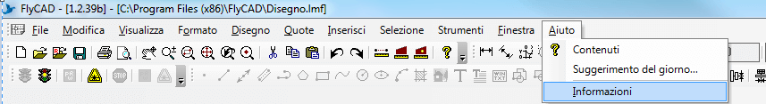
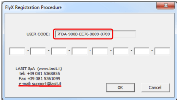
If you changed your laser or your computer you will have to insert the registration code in FlyCad software, otherwise the laser will result disabled and thus not working.
First thing, be sure that the laser is on and that it is connected to the computer through the network cable.
Open FlyCad and select from “Help” menu the voice “About”

The software will display a window in which you will find all the information relating to the installed FlyCad version and the Registry Code. Click on the 3 dots labeled button, as shown in the picture below.
In the displayed window take note of the user code and send it to [email protected].
You will get from us another code you will have to insert in white boxes.

This modality involves the utilization of the laser with no communication with FlyCAD. When this modality is on it is possible to send some commands to the LASER unit via RS232 serial door from a PLC or from another device.
To see the available commands check the paragraphs:
– Simplified SERIALJOB2 protocol
– StanAlone protocol with no control features